
This rulebook is now old! Please see this page for the development of the new rules.
The PDF version of the rulebook, V1.5, is available here!
Please check this page regularly as the latest PDF rulebook, changelog and any amendments that have not yet made it into the PDF version will be posted here. The latest PDF, *plus* the amendments listed on this site, are considered the reference for the competition.
Please post any questions and comments to the mailing list, http://list.oarkit.org/ , for group discussion.
Proposed changes:
Mapping and Autonomy (P14, Section 1.4):
NOTE: This replaces the Exploration section in Major since, in RMRC, we would like to focus more on developing advanced sensing on these smaller platforms and few (if any) teams have mapping and/or map-based autonomous exploration capability. Should we still have some Exploration/Mapping in here? Discuss at http://list.oarkit.org.
We have now had several teams express an interest in mapping and autonomous exploration. We are proposing to add a mapping and autonomy test as follows.
Construction:
- Maze with wooden (not clear!) walls, at least 30 cm above the support surface (floor, terrain, etc.).
- 30 cm minimal lateral clearance at all points.
- Progressively more complex flooring (starts flat, then continuous ramps, crossing ramps, kerbs). Proposing no “red” terrain elements (stepfields) and no precision elements (eg. parallel rails).
- For ease of construction, most of the maze will probably be on a 30cm grid but we will have some parts that aren’t to ensure that mapping works even when this isn’t the case.
- It should be clear that the robot isn’t making use of prior information about the maze layout in building the map (eg. prior run data, information provided by the operator, snapping to a known grid, etc.).
- Discuss at http://list.oarkit.org – what should the map layout look like?
Running:
- The robot starts and may be driven through the arena.
- Robots that are able to demonstrate autonomy during practice have the option to receive twice the amount of time (a double slot) if they run without operator intervention.
- Physical intervention (and remote intervention for autonomous runs) result in a reset and a new ‘mini mission’. Note that the mapping data must be cleared between mini missions.
Evaluation:
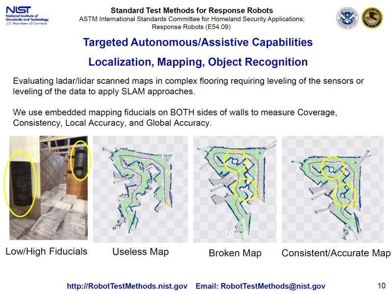
- We will have mapping fiducials (cylindrical features, 15cm in diameter, that sit across a wall so only one half is visible at a time) to evaluate your map quality. On a good map the two sections will line up, on progressively poorer maps they will not. We will place these fiducials in locations consistent with the 30 cm lateral clearance.
- We propose 0.5 points for each half-fiducial that is recognisable (as points for coverage of the arena) and an additional 1 point for each fiducial where both halves match up (to within a fiducial radius). Thus a good map will yield 2 points per fiducial.
- We will also be comparing the map to a groundtruth obtained by photographing the maze from above just before the start of the run. This is proposed to be for illustrative purposes rather than for assigning points.
Sensing (P14, Section 1.4.1):
Manual vs Automatic Detection:
A standard 30 cm (12 in) crate with several sensor tests as shown in Figure 14 is placed in front of the robot. The tests are Visual/Thermal Acuity (the black areas of the Landolt-C optotypes are heated), Motion (the disc with black spot rotates), Colour Acuity, Hazmat Label, Audio Acuity and CO2.
The purpose of the crate is to both limit the access of the robot to the test artefacts as well as to introduce complex lighting to the problem.Motion must be automatically detected. The display to the operator should show a smooth indication of detected movement around the moving black spot. Indicators should not appear in other areas of the image that do not correspond to moving objects in the environment.
The hazardous materials labels must be automatically detected and recognised. The location and identity of the labels should be indicated in the video displayed to the operator. No objects that are not hazardous materials labels should be indicated and the same region should not be indicated as multiple labels. There should be no operator intervention in the detection and recognition of the labels.
Proposed points allocation is as follows. Tests marked (operator) require the operator to observe and interpret their OCU display. Tests marked (automatic) need to be interpreted automatically.
The scenario behind the sensor tests marked (automatic) is that they are proxies for tasks that the robot should be doing in order to take the load off the operator, who may be concentrating on driving and not able to look at all the camera feeds at once.
We don’t require that all of their displays be up all the time but if the various detectors are in different tabs of the interface, it should be clear to the judge that the task is still running during the sensor test (and not producing spurious detections and identifications). What we don’t want is a situation where the operator is effectively doing the ‘detection’ for the system by flipping to the relevant tab or window only when there is something interesting to detect.
One way of doing this might be to have some kind of notification area showing a summary of the detection status of each detector, regardless of if their window is shown or not. This makes it easy for the judge to see when the detectors have and haven’t detected something without operator intervention.
We do not care if the image processing happens on the robot or on the operator station. In the scenario, it should be happening on the robot but we don’t want to penalise teams that may not be able to afford high performance embedded computers. We do need detection to run in a timely manner though (as a guide, it should update at least once every 2 seconds with a similar delay) and can’t make guarantees about the state of the internet connection so don’t rely on throwing compute tasks up to the cloud.
The detection and identification of the artefact (label, QR code, etc.) needs to be stable when the robot is stationary in front of the sensor test. No points will be awarded if the detection flickers in and out (the *occasional* flicker out that comes back immediately is OK). Similarly, no points will be awarded if the identification flickers between multiple identities (eg. continuously flickering between “Flammable” and “Flammable Gas”).
For this year, the operator is welcome to position the robot for a good detection (eg. turn on the robot’s lights, square up the camera to the label, etc.) but it should be clear that the operator isn’t ‘helping’ the system come to a decision as to if the label is there or its identity.
This year we are also not requiring the detection and identification software to run outside the sensor (and survey acuity) tests but the team does need to demonstrate that the robot is at least driveable through the OCU when the detection and identification software is running.
Points Allocation:
We have had some questions about points allocations. Please don’t worry so much about the absolute values of the points allocation; because everything is normalised anyway, we only care about the relative points for each sensor test.
– Visual Acuity (operator): 1 point for correctly identifying the orientation of the 8mm gap, 1 point for the 3.2mm gap, across 2 Landolt Cs yields 4 points total.
The first point per optotype (2 points per crate) is intended to be the “easy” point of the test.
To reward better vision, it is proposed that we award 1 point for the ring with the 3.2 mm gap, 1 point for 1.3 mm (and no points for the 8 mm gap).
Optotype direction should be reported (by visual observation by the operator) as one of the following:
- Up
- Up-Left or Left-Up
- Left
- Down-Left or Left-Down
- Down
- Down-Right or Right-Down
- Right
- Up-Right or Right-Up
The operator should also show the judge the display to demonstrate that the direction can be clearly identified. No score is awarded for a ring if the ring has more than one break (region of similarly lighter pixels).
– Thermal Acuity (operator): 1 point for detecting the presence of heat, 1 point for the 20mm gap, 1 point for the 8mm gap, across 2 Landolt Cs yields 6 points total.
This effectively translates into 1 point for having a directional heat sensor, 1 point for a rudimentary thermal camera (or a scanning array sensor), 1 point for a higher resolution thermal camera (or one mounted to an arm that can be placed closer to the target).
– Motion (automatic): 2 points for detecting and tracking the black spot, across 2 disks yields 4 points total.
– Colour (operator): 0.5 points for correctly identifying each coloured square, across 5 colours, across 2 labels yields 5 points total.
The colours should be identified as one of the following, taken from the colours of standard hazmat labels (US 2009 CFR Title 49, Volume 2). Pantone colours are a rough indication, there will be variations due to the capability of the printer and lighting conditions. The operator performs this identification and will be provided with a set of colour samples printed on the same printer as the targets. Automatic detection is not necessary.

– Hazmat (automatic): 3 points for correctly identifying each label, across 2 labels yields 6 points total.
We will be using the placards available from http://ian-albert.com/hazmat_placards/ .
There are a couple of ways of doing this task, for example teams may choose to detect each variation of each label as a separate entity (so “Explosive 1.3” is considered as different to “Explosive 1.4” as to “Flammable Liquid”) and do basic image matching. Alternatively, teams may choose to do some kind of decomposition of the label into constituent parts such as background colour, symbol, letter and so-on, that are then detected as a label.
We don’t say anything about which of these approaches (or any other approach) is the right one.
A few more notes:
- We will be printing the labels using a standard office printer and there will be variations in lighting at the venue (remember, the label is also going to be inside a milk crate so there will be shadows) so effective solutions will need to accommodate variations in both actual and apparent colour.
- For the full 3 points each, the labels will need to be detected and identified completely correctly. Where the identification is imperfect, we will award sub-points as follows:
- 1 point for the detected label background matching. Must be a full match. Detecting “Flammable Gas”, which has a full red background, as “Spontaneously Combustible”, which has a half red, half white background, doesn’t count.
- 1 point for the detected symbol matching. Note that “Oxidizer” and “Flammable” are different symbols.
- 1 point for the text matching.
– Audio acuity (operator): 8 letters/numbers read out, 0.5 points for each correctly identified, 4 points total. Note that this does NOT need to be done automatically. Expect conversational volume levels (easily understood by a typical human in the same position as the robot) in ambient noise typical of a convention/competition environment (ie. general noise but not necessarily cheering).
– CO2 (operator): 2 points for demonstrating an increase in CO2 level when a CO2 source is exposed to the robot (eg. human breath or compressed CO2 canister). This year we will permit teams to release the CO2 source anywhere (including up against the robot). In future years, this will be released from the back of the crate and robots will need to detect the rise in concentration from the front of the crate.
There is a suggestion that we can allocate an additional 2 points (for 4 in total) for detecting the CO2 source from the front of the crate. I’m a little bit reluctant to go with this until we can come up with some way of making this consistent. Until we come up with a plan, I’m inclined to leave this rule as it is. Don’t agree? Have ideas? Discuss at http://list.oarkit.org .
Additional misc. to-do items:
- Statement about prototypical tests
- P7-8, Section 1.1.1 Centre: Clarification about 120% lateral clearance to compensate for quantisation.
- P10, Section 1.2.1 Hurdles: Clarify that we’re talking outer diameter.
- P12, Section 1.3 Dexterity: Clarify size of dexterity board vs terrain, update picture. Clarify the role of the terrain in penalising repositioning of the robot base. Clarify how we’re setting up the pipes (all same task, different tasks, etc.).
- P17, Configuration Management: Equipment available (metered backdrop, scale, tape measure).
- P17, 1.6 Drop Test: Change heights to 0.5 m and 1 m.
Open Questions for Discussion:
- Forces for touch points test with lights?
- Incorporating manipulation and survey acuity into the multiplier?
- Size of pipestars?
- CO2 detection at a distance, making it consistent?
Amendments since version 1.5:
(None yet.)
Changelog
V1.5
- First version openly published. Major changes from any previous version, consider the entire document to be new.